Calculations with Logic Gates: Full Adders and Half Adders
This post takes a look at how we can start to build a computer using logic gates by taking a look at how we can produce a circuit to do addition.
You might be familiar with the process of adding up numbers by hand:

Binary numbers can be added on paper in exactly the same way:
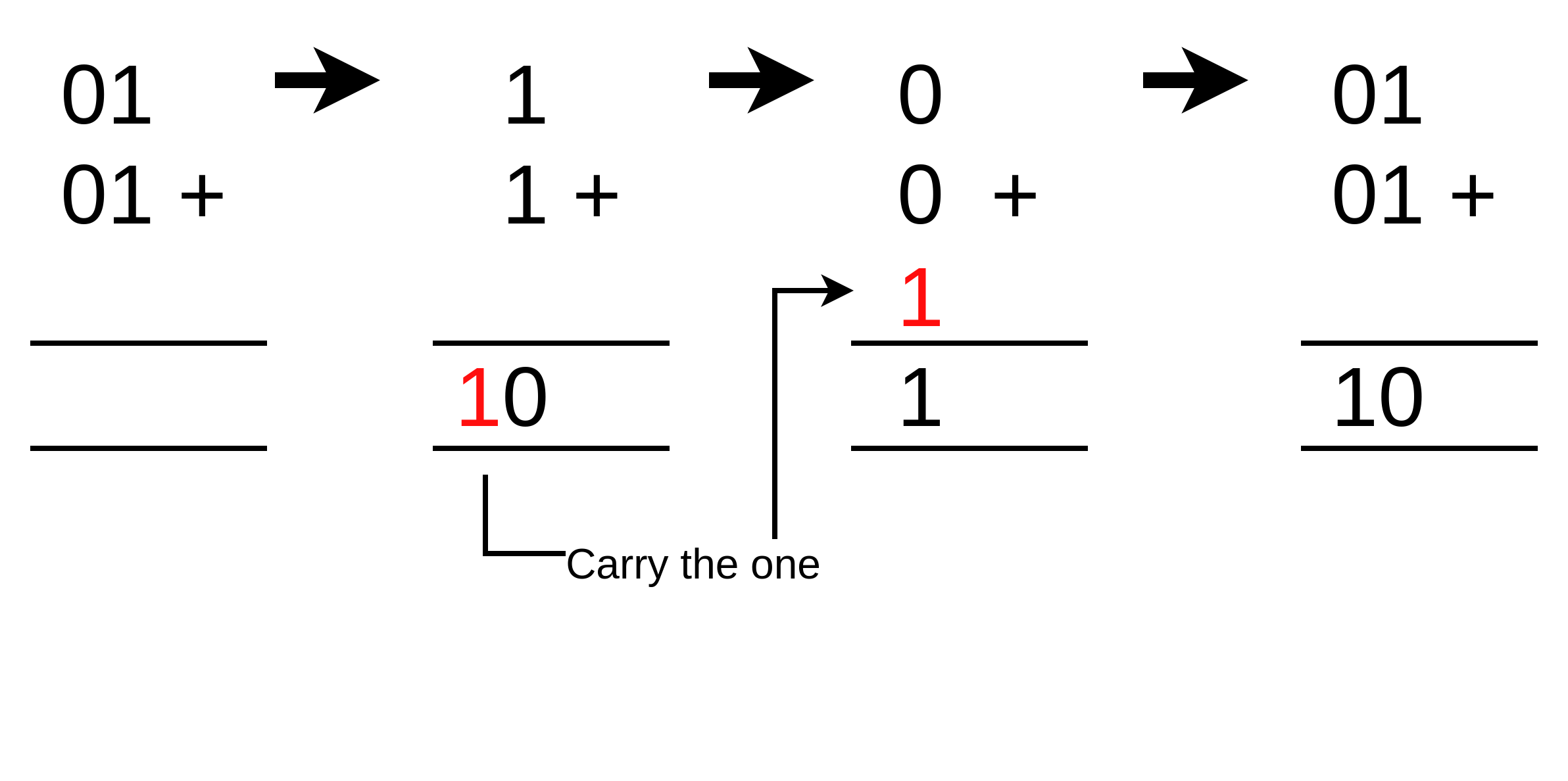
If we look closely at the process of adding one of the columns of binary digits only, there are four possible combinations of the two digits. The top digit can be 1 or 0 and the bottom digit can be 1 or 0. The result of the addition is one digit, but in one situation, when both of the digits are 1, we also get the carry bit.
We can write out everything that can possibly occur when adding a single column of two binary digits as follows:
| 1st Digit | 2nd Digit | Addition Result | Carry |
|---|---|---|---|
| 0 | 0 | 0 | 0 |
| 0 | 1 | 1 | 0 |
| 1 | 0 | 1 | 0 |
| 1 | 1 | 0 | 1 |
If you look at the addition result column, you may notice something familiar. As a reminder, take a look at the truth tables for logic gates. It’s exactly the same as the truth table for an XOR (exclusive or) gate. Let’s look again at the truth table for this gate:

| Input A | Input B | Output |
|---|---|---|
| 0 | 0 | 0 |
| 0 | 1 | 1 |
| 1 | 0 | 1 |
| 1 | 1 | 0 |
Now take a look at the “Carry” column. It’s exactly the same as the truth table for an AND gate:

| Input A | Input B | Output |
|---|---|---|
| 0 | 0 | 0 |
| 0 | 1 | 0 |
| 1 | 0 | 0 |
| 1 | 1 | 1 |
So, the implication from this is if we combine these two gates together, then we can make a circuit for adding up the two binary digits in the right hand column:

This circuit is called a half adder.
That’s the right column done. But what about the left-hand column? We can almost use the same circuit again, but there’s a problem: there’s only two inputs. We need a way to pass in the carry result coming from the right column and add three binary digits. The solution to this is we can glue two half adders together to add a third digit to the calculation like this:

What’s happening here?
- There’s one half adder connected to the two digits in the left column of the addition. The AND gate in the first half adder is letting us know if there is a carry bit from the calculation result from the two digits.
- The second half adder is taking the result from the first half adder, then adding it to the carry bit that’s arrived from the right column. So now we have three binary digits added together. This calculation may itself produce another carry bit.
- Now we have the situation where there are potentially two carry bits coming from either or both of the two half adders. We use an OR gate to say if either or both of the two half adders have produced a carry bit, then we output a carry bit. This could be passed onto a third column of digits.
This circuit is called a full adder because it provides everything that is needed to do addition of two binary digits in all circumstances, whereas a half adder only works if there is no carry in.
Now let’s put it all together with a circuit to add two three digit binary numbers. When we draw a lot of logic gates the circuit starts to get confusing, so we simplify it by using blocks to represent groups of logic gates that are repeated. Here we represent the bunch of logic gates for full adders and a half adder using a square but don’t actually draw the gates. The two digit inputs from the addition are called “A” and “B”. The carry input is shortened to “Cin” and the carry output is shortened to “Cout”. The output for the adders we will call “S” to mean sum.
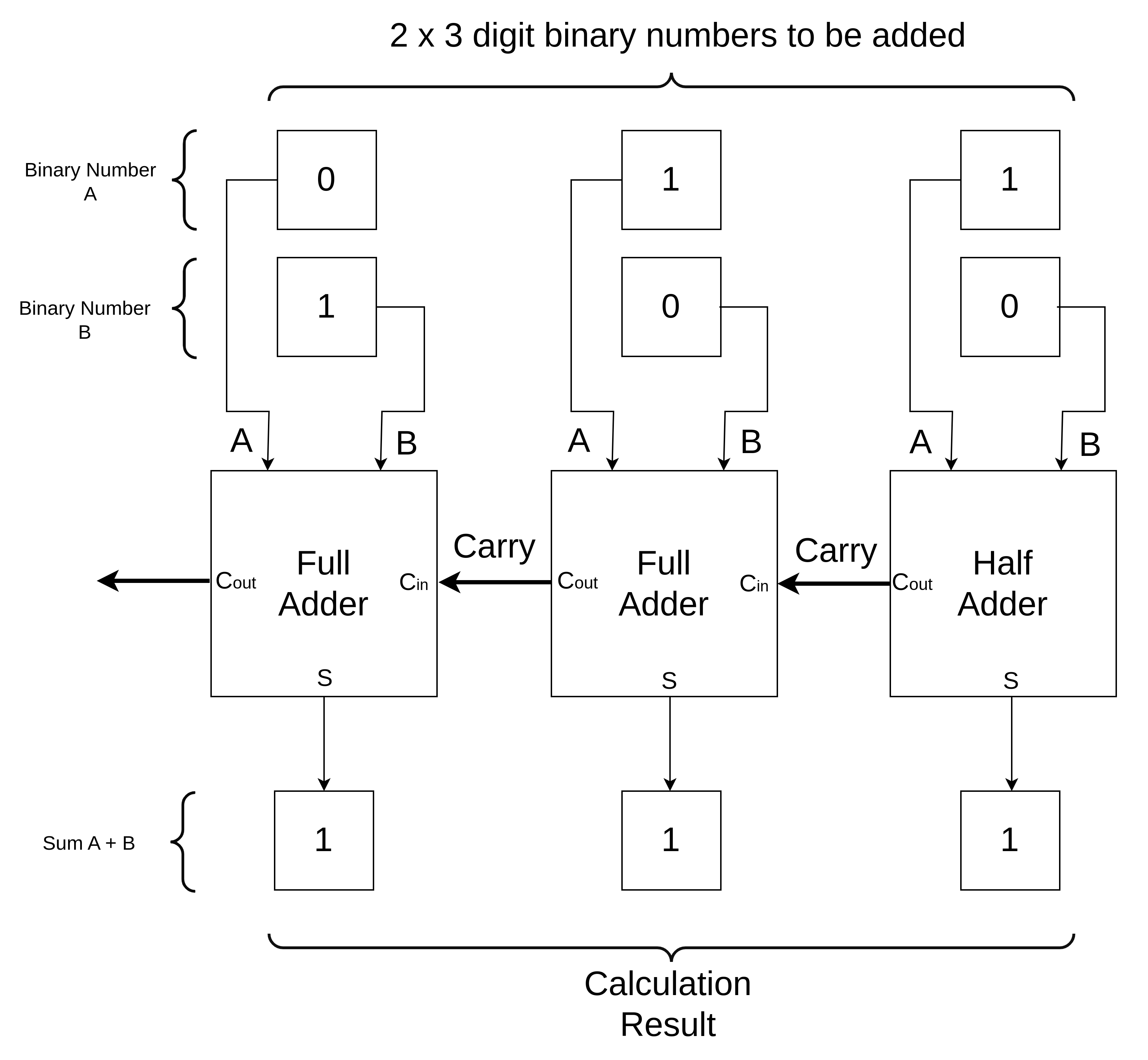
Why do we bother using a half adder for the first digit when a full adder block can do everything anyway? The reason is that the half adder has fewer logic gates. Computer chips have only limited space for gates and the fewer gates we can use, the cheaper the chip can be (or the more functionality it can have). We only ever use the minimum number of gates that are required. The full adders need 5 gates but the half adder only needs two. The right-most digit of the addition does not require a carry in and so a half adder will do.