An Introduction to Electronic Logic Gates
Why are Logic Gates Important?
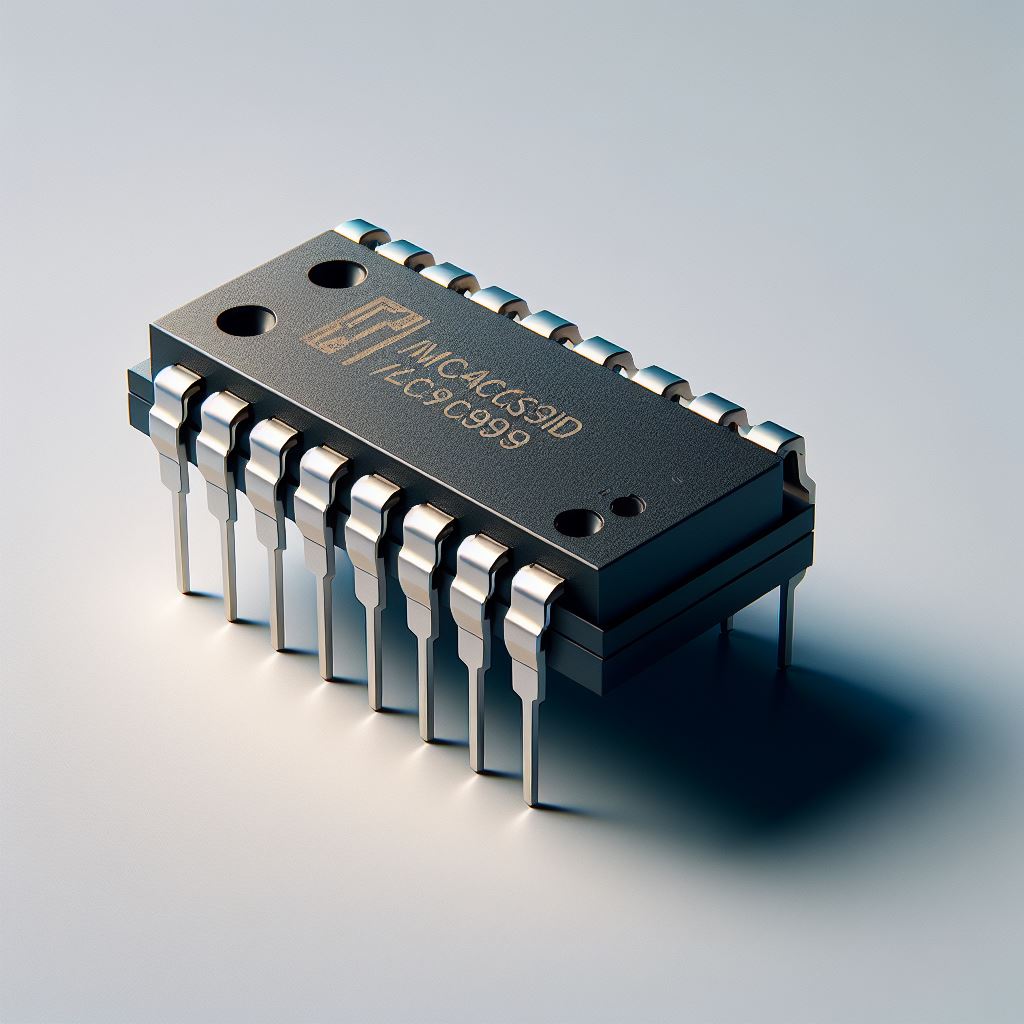
All digital computing chips are composed of the same few basic circuits repeated over and over again in different patterns many millions of times. These basic circuits are known as logic gates. The gates are built out of electronic components called transistors and microchips contain almost entirely transistors. To simplify drawing out diagrams of digital circuits, the actual transistors that comprise the gates are not shown and the gates are instead represented by a common set of symbols that electronic designers have agreed upon. When you see one of these symbols, it’s actually representing a bunch of transistors on a chip that perform the gate operation.
The following list of logic gates is enough to build any digital computer. Even the most sophisticated CPUs and graphics cards found in the latest computers are just combinations of this set of gates arranged in different ways.
Logic gates work in binary and it is assumed the reader is already familiar with binary. Binary is used as a way of representing current flow in the actual electronic circuit. When we have a binary “1”, the current is flowing in the electrical circuit. When we have a binary “0” there is no current flowing. For example we may represent the state of a lamp in binary. When the lamp is switched on, current is flowing through the wires, we might call this is a “1” state. When the lamp is switched off, we might call this a “0” state.
Basic logic Gates
The “NOT” gate (also called an inverter) is the simplest gate and the symbol is shown below. It has one input and one output. If you put a 0 in then it produces a 1 out of the other side. If you put a 1 in, then it produces a 0. Note that the symbol for a NOT gate has a small circle on the end. This same small circle appears on other gate symbols as well to mean inversion.

The “AND” gate is usually shown with two inputs (but can have more than two inputs) and one output. This gate requires that all of the inputs are a 1 in order to get a 1 out. In any other situation it produces a 0. That is, A AND B must be 1 to get a 1 out.

The operation of gates is often explained in a table form and is known as a truth table. A truth table shows every possible input and every possible output for an electronic circuit. The truth table for an AND gate is as follows:
| Input A | Input B | Output |
|---|---|---|
| 0 | 0 | 0 |
| 0 | 1 | 0 |
| 1 | 0 | 0 |
| 1 | 1 | 1 |
The “OR” gate will produce a 1 as the output if any of the inputs at all are 1 in any combination. It will only produce a 0 if all of the inputs are 0. That is if either A OR B are 1, then it produces a 1 at the output.

The truth table for the OR gate is as follows:
| Input A | Input B | Output |
|---|---|---|
| 0 | 0 | 0 |
| 0 | 1 | 1 |
| 1 | 0 | 1 |
| 1 | 1 | 1 |
The “NAND” gate is an AND gate connected to a NOT gate. The small circle on the symbol gives us a hint that it’s going to perform a NOT operation at the output. So this gate does the same as the AND gate but produces the exact opposite output. If both of the inputs are zero, then it produces a 1 out. If either of the inputs are a 1, then it produces 1 output. It only produces a 0 if both of the inputs are a 1.

| Input A | Input B | Output |
|---|---|---|
| 0 | 0 | 1 |
| 0 | 1 | 1 |
| 1 | 0 | 1 |
| 1 | 1 | 0 |
Similarly, the “NOR” gate is an OR gate connected to a NOT gate. Again the symbol has a small circle attached to the end of an OR gate, implying it has a NOT gate attached to the output. Hence if any of the NOR gates inputs are a 1, then it produces a zero out. Only if all of the inputs are 0, then it produce a 1 out.

| Input A | Input B | Output |
|---|---|---|
| 0 | 0 | 1 |
| 0 | 1 | 0 |
| 1 | 0 | 0 |
| 1 | 1 | 0 |
The Apollo Guidance Computer, used to fly to the moon, was built almost entirely out of NOR gates.
The gate below is called an “exclusive OR gate”, commonly written as “XOR” for short and is a little more unusual. This gate produces a 1 at the output if either of it’s inputs are 1, but not both. If both of the inputs are a 1, then it produces a 0 output i.e. it only produces a 1 if only one of the inputs are a 1 exclusively.

| Input A | Input B | Output |
|---|---|---|
| 0 | 0 | 0 |
| 0 | 1 | 1 |
| 1 | 0 | 1 |
| 1 | 1 | 0 |
But how can logic gates be used to build a computer? We will begin to explore this in the article: Calculations with Logic Gates: Full Adders and Half Adders.
